SysCONNECT SL-800 Modem Upgrade Installation Instructions
The Systech SysCONNECT Modem may be used to upgrade an existing Systech SysLINK Modular IoT Gateway with a new cellular modem. This document describes how to perform the physical upgrade of an existing gateway.
Summary (with links)
Instructions for SysLINK SL-800
Your upgrade kit contains the following items.
Screws (2)
Washers (2)
Internal antenna wires (2)
Cellular modem card


Alternative form-factor
Tools you will need.
Medium flat-blade screwdriver
#1 Phillips screwdriver
Small flat-blade screwdriver
8mm wrench
To help prevent damage, you should wear a static wrist band throughout the upgrade process.

1. Update Software
Support of the SysCONNECT Modem requires SysLINK Core software version 01A.22, or later. For CZ4B and CV1B modules, need version 01A.42 or later.
Also, PPP package version 2.4.7, or later is required.
Save the above two files on a local PC.
If the gateway or local PC is not already part of a local LAN, connect the local PC to the LAN port of the gateway with an Ethernet cable.
Open a web browser (Ex: Chrome). If the local PC is connected directly to the gateway, you may receive a connection error message. That is OK.
In the address line of the web browser, enter the IP address of your unit (Ex: https:\\192.168.1.90:7444), followed by Enter.
You should see the Welcome screen for the gateway.
When prompted, enter the username and password of the gateway. Contact your VAR or Systech if you need help with your username or password.
Select Flash Management in the menu
In the Flash Update section, click Browse, locate the file you saved above and click OK
Click the Update Flash button
The unit will take time to load different packages and return with “Request Succeeded”.
Once finished loading all packages, reboot using the Reset/Reboot menu and Reboot.
Additionally, update the SysLINK configuration following the steps below. If updating multiple SysLINK gateways, you may consider saving the configuration of one updated gateway, and loading the updated config file to all other gateways. Alternatively, you may also consider using the SOUP management software to update gateways over-the-air.
1. Login to the SysLINK Web UI.
2. Click the PPP settings.
3. Click on Edit
4. Paste this text:
ABORT BUSY
ABORT 'NO CARRIER'
ABORT ERROR
TIMEOUT 45
'' AT
OK
ATD*99***3#
CONNECT
5. Click Save Changes
6. Click on Reset/Reboot link in the left-most pane to go to Reset/Reboot page.
7. Click Reboot.

2. Open Gateway Enclosure
There are two slots at each edge of the gateway. Using the small flat-blade screw driver, gently pry up in one edge to release the enclosure.

3. Remove SMA Connectors From Enclosure
The existing SMA connectors must be upgraded along with your new cellular modem. Unplug the two antenna cables from the old modem module. Using the wrench, remove the two SMA connectors.
If your gateway supports Wi-Fi in addition to cellular, be sure to remove only the cellular SMA connectors. These are the connectors that were originally connected to the old modem.


4. Remove Old Modem
Remove the two screws & washers from the old modem module (see red arrows in picture below) with the Phillips screwdriver.
Remove the old modem from the mini-PCIe connector. It should slide out horizontally. The old modem may be discarded.


5. Insert Your SIM
Locate the appropriate cellular SIM. The SysCONNECT uses the 4FF (nano-SIM) form factor.
With the metal contacts toward the bottom, carefully insert the SIM into the SIM socket on the new modem. The small notch in the corner of the SIM must be located on the back edge (trailing edge) of the SIM card as you insert it. See the picture. Slide the SIM entirely into the socket, with no part of the SIM hanging out. There is no internal spring, or click.
In the future, to remove the SIM from the SIM socket, a SIM removal wire can be used to push the SIM back out of the socket. Alternatively, a thin paper clip may also be used.
Although there may be additional SIM sockets on the motherboard, only use the SIM socket on the new modem card.


Alternative form-factor SIM insertion
6. Install New Modem Card
Insert the new modem card into the mini-PCIe connector. Be sure to slide card fully into the connector. The back end of the modem card will angle up naturally until you install the mounting screws.
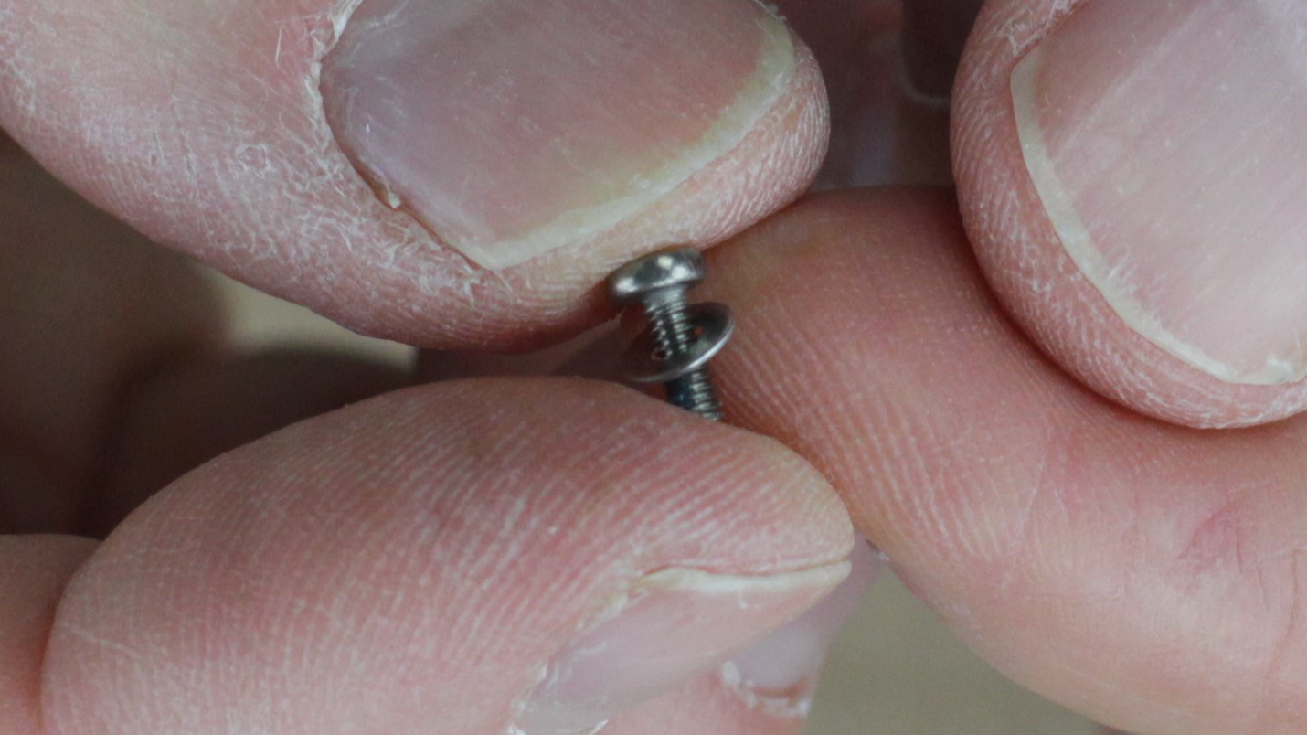
Slide the washers onto the screws prior to mounting.
Install the two screws (with washers). Do not overtighten.

7. Add New SMA Connectors
Use the wrench to install the new SMA connectors to the plastic enclosure in the same location as the old SMA connectors. Note that the SMA connectors have one side that is slightly flat. Be sure to align the flat side of the SMA connector to the flat side of the opening in the plastic enclosure.
Slide the washer on the connector on the outside of the enclosure. Then install the flat nut, and tighten. Do not over-tighten.
Note: The wire color of the new SMA connectors may be grey or black.

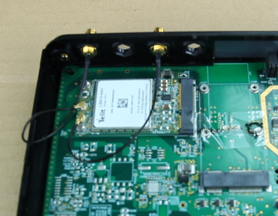
8. Reconnect the Antenna Wires
Connect the antenna wires to the small U.FL connectors on the new modem card. It is important to connect the wires to the appropriate location. The wire labeled "Main" must be connected to the U.FL connector further from the edge of the new modem card (identified with a small letter M). The wire labeled "Aux" must be attached to the U.FL connector closest to the edge of the new modem card (identified with a small letter D).
It is best to ensure the wire connector is flat (parallel to the board), so the connector can be pressed straight down until it snaps into place. It is correctly installed when the connector can be slightly rotated without becoming loose.

Alternative form-factor connections
9. Close the Enclosure
Rotate the top of the enclose to ensure the surface ridges of the top and bottom are opposite of each other (see image below). Then carefully press the top and bottom enclosure pieces together, pressing at each edge. This may require significant pressure to ensure a tight seal.

10. Apply Cellular ID Sticker
Apply the enclosed sticker that identifies your new modem's MEID information.
